|
|
 |
|
My first computer. Control Data 3170.
Installed at
Studentsamskipnaden in 1972, running administrative routines for the
University bookshop, student lodging, internal
accounting, payroll, etc. Job assignment: Systems Analyst. |
|
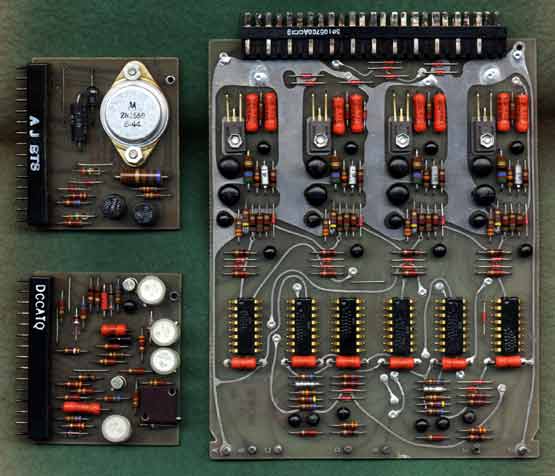 |
The
electronic circuit boards employes discrete components, i.e. transistors, resistors, capacitors, aso. The two left circuits were taken from the printer controller, the larger to the right comes from the disk controller and contains 6 IC (intergrated circuits) each with 8 pairs of legs. |
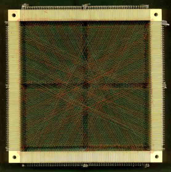 |
Each cabinet (behind the disk drives - see top
picture) contains a
core memory stack with neccessary control logic, each 16K words of
memory. 1 word = 24 bits, 1 character = 6
bits. The name "core memory" comes from the fact that the memory was built up by ferrite core rings. These were manually produced in the far East, were girls were sowing the core mats by hand. |
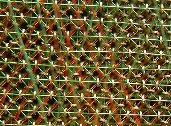 |
Detail of the above core stack. The ferrite core
is clearly visible in the picture as small brown rings, each has 4
electric leads passing through the ring for storing and reading
data. 1 ferrite core ring = 1 bit of data. |
 |
Input to the computer was mostly thru usage of
punched cards. A card has 80 columns, i.e. up to 80 characters could be
punched on a card. Each column has 12 rows, the lower 10 are numbered 0 - 9. By punching different hole combinations, different characters could be represented. E.g. letter "D" has holes in rows top and 4. |
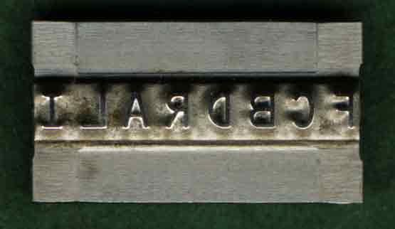 |
Output from the computer were mostly produced on paper. The printer was mechanical, either a drum printer (501), or a chain printer (512): a printer slug is pictured here. The whole character set was mounted on a chain of slugs, this chain quickly rotated in front of the paper while a row of hammers on the other side of the paper hit the correct character at the right time to produce printing on the paper. The 512 printer was able to print up to 1200 lines per minute. |
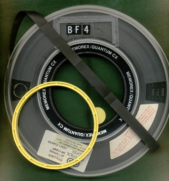 |
Other input and/or output media were magnetic
tape. A full 2400 ft. tape could store up to 80 Mb data at 6250 cpi. Tape width is 1/2" = 12,7mm. The pictured tape is a high-quality 1200 ft. tape. The tapes were mostly used for backup purposes. Notice the yellow ring. This is the "write protect" ring, and was inserted on the back of the reel when the tape was rewritten. Removing the ring protected the tape from being (accidentally) over written.
CDISK |
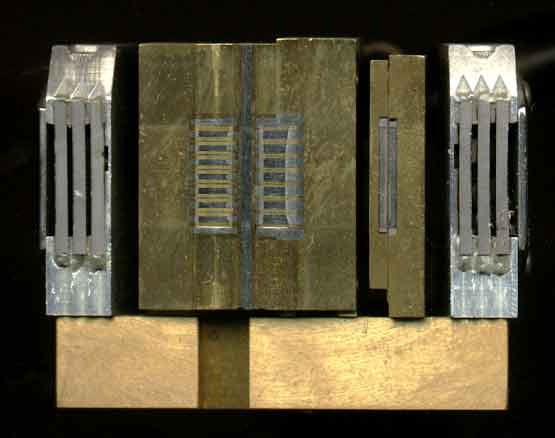 |
The magnetic tape reading / recording head. This is a 7 track tape head, 6 tracks of data and 1 track parity check. Data could be recorded in 200, 556, or 800 bpi. 9 track tapes succeeded, with much higher density (1600cpi or 6250cpi). |
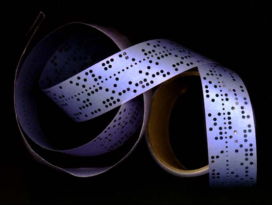 |
Paper-tape was much less used as input (or output)
medium. Mostly because it very easily got damaged. However, we did have a paper-tape reader (RC Danish make) and a standard CDC paper punch. |
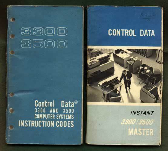 |
The operating system was MASTER. Pictured here are the quick reference manuals of machine instruction codes (Assembly language COMPASS), and the job control language MASTER instant manual.
MASTER was multitasked and had virtual memory, but memory management was primitive. Entire programs (tasks) had to be swapped out to disk to free memory. |
|
ECODU 19 Amsterdam |
This is a presentation given at ECODU 19 in Amsterdam.
It was never published in the proceeding for security reasons. It is
nearly 30 years ago this presentation was given, so the security risk
today is about nil. Wonder if there are any MASTER systems still running?
I take the chance now to publish it... It is interesting to note that the techniques described here are actually one of the first documented hacker attempts to break into a computer system:
however, the purpose was to "wake up" the vendor to improve and secure system against abuse.
ECODU = European COntrol Data
User group. |
|
OLP |
OLP overlay linking processor My first assignment at the Studentsamskipnaden was as a student summer job. They had problemtswith a FORTRAN program that was overflowing memory limit. This problem could be overcome by the OVERLAY technique, but this would require considerable reprogramming of the application. OVELAYs required that no modules in the overlay could be called from the main program area. You could only call the overlay. However, code in the overlay may call modules in the main area. The application required calls in both directions. OLP made use of OVERLAYs, but solved the linking of module calls from main to overlay at runtime. The solution patched all binaries, inserted a binary runtime linking module tailored at the application for maximum performance. |
|
JOB composer |
JOB Composer My last project at the Studentsamskipnaden. In an attempt to make a compact and efficient interactive batch system, I wrote the JOB Composer. It consumed 4qp (2K words) memory and was multi-threaded. The purpose was to replace the punched card, to be able to submit jobs and inspect job results. This experiment was carried out at the end of my carrier at Studentsamskipnaden, and was not pursued further as a product. However, the JOB Composer was actually used in Austria at the University in Wien with very good feedback. It was coded in assembly (COMPASS), but made use of pseudo-code to document and assist in coding. The pseudo-code looked much like SIMULA. It was interesting to see that during development and debugging, that functional errors discovered often were present in the pseudo-code aswell as the assembly code! Time moves on, everybody converted to CYBER systems (or other vendors), were interactive systems were much better suited and implemented. |
| Ref.manuals |
Cobol manual Fortran manual Compass manual See also
CD3000 document archieve. |
|
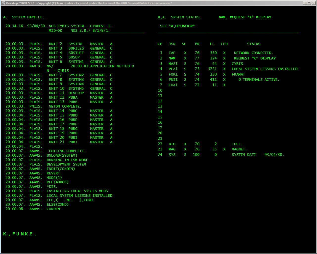
CYBER
many years later a Cyber emulator running
on an
|
CDC CYBER computer systems installed at
various places where I had several large and smaller projects and developments.
|
|
|
|
| Image created in 2023. | |